Search
power generation and storage

Optimum Solar Conversion Cell Configurations
A solar cell manufactured from this new optical fiber has photovoltaic (PV) material integrated into the fiber to enable electricity generation from unused light, including non-visible portions of the spectrum and visible light not transmitted to a lighting application. These new solar cells are based around cylindrical optical fibers, providing two distinct advantages over the flat panels that lead to increased efficiency. The core fiber, used to transmit light, can be adjusted to increase or decrease the amount of available light that is transmitted to the lighting application at any point in real time. This invention can be applied wherever optical concentrators are used to collect and redirect incident light. Wavelengths as large as 780 nanometers (nm) can be used to drive the conversion process. This technology has very low operating costs and environmental impacts (in particular, no greenhouse gas emissions). The fiber uses low-cost polymer materials. It is lightweight and flexible, and can be manufactured using low-cost solution processing techniques. Such multifunctional materials have great potential for the future of solar and photovoltaic devices. They will enable new devices that are small and lightweight that can be used without connection to existing electrical grids.
sensors

Lightweight Fiber Optic Sensors for Real-Time Monitoring of Structural Health
<strong><i>How It Works </strong></i>
The FOSS technology employs efficient, real-time, data driven algorithms for interpreting strain data. The fiber Bragg grating sensors respond to strain due to stress or pressure on the substrate. The sensors feed these strain measurements into the systems algorithms to determine shape, stress, temperature, pressure, strength, and operational load in real time.
<strong><i>Why It Is Better </strong></i>
Conventional strain gauges are heavy, bulky, spaced at distant intervals (which leads to lower resolution imaging), and unable to provide real-time measurements. Armstrong's system is virtually weightless, and thousands of sensors can be placed at quarter-inch intervals along an optical fiber the size of a human hair. Because these sensors can be placed at such close intervals and in previously inaccessible regions (for example, within bolted joints, embedded in a composite structure), the high-resolution strain measurements are more precise than ever before. The fiber optic sensors are non-intrusive and easy to install—thousands of sensors can be installed in less time than conventional strain sensors and the system is capable of processing information at the unprecedented rate of 100 samples per second. This critical, real-time monitoring capability enables an immediate and informed response in the event of an emergency and allows for precise, controlled monitoring to help avoid such scenarios.
<b><i>For more information about the full portfolio of FOSS technologies, see DRC-TOPS-37 or visit <a href=https://technology-afrc.ndc.nasa.gov/featurestory/fiber-optic-sensing>https://technology-afrc.ndc.nasa.gov/featurestory/fiber-optic-sensing</a></b></i>
sensors

Sensing Magnetic Fields
This technology is part of Armstrong's portfolio of fiber optic sensing technologies known as FOSS. The innovation leverages Armstrong's cutting edge work in this area, including its patented FBG interrogation system, which allows for a diverse set of engineering measurements in a single compact system. In addition to magnetic field, other measurements include structural shape and buckling modes, external loads, and cryogenic liquid level. The system and measurement technology is commercially available for research applications. In addition to capitalizing on the significant advancements in fiber optic and laser technologies that have been made to support the telecommunications industry, Armstrong has also partnered with UCLA's Active Materials Lab (AML) to tap their expertise in the field of magnetics.
<b><i>For more information about the full portfolio of FOSS technologies, see DRC-TOPS-37 or visit <a href=https://technology-afrc.ndc.nasa.gov/featurestory/fiber-optic-sensing>https://technology-afrc.ndc.nasa.gov/featurestory/fiber-optic-sensing</a></b></i>
Optics

3D Lidar for Improved Rover Traversal and Imagery
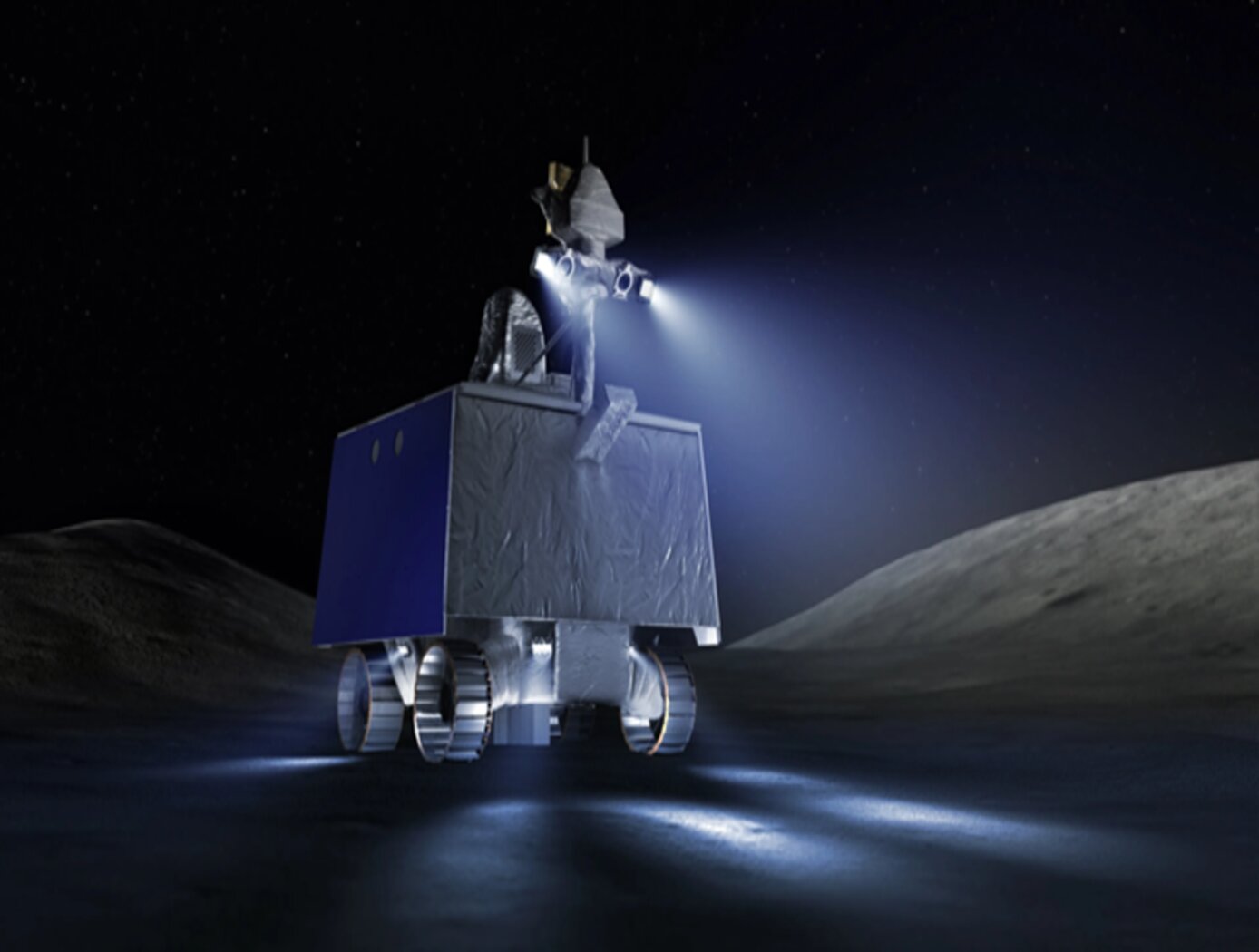
The SQRLi system is made up of three major components including the laser assembly, the mirror assembly, and the electronics and data processing equipment (electronics assembly) as shown in the figure below. The three main systems work together to send and receive the lidar signal then translate it into a 3D image for navigation and imaging purposes.
The rover sensing instrument makes use of a unique fiber optic laser assembly with high, adjustable output that increases the dynamic range (i.e., contrast) of the lidar system. The commercially available mirror setup used in the SQRLi is small, reliable, and has a wide aperture that improves the field-of-view of the lidar while maintaining a small instrument footprint. Lastly, the data processing is done by an in-house designed processor capable of translating the light signal into a high-resolution (sub-millimeter) 3D map. These components of the SQRLi enable successful hazard detection and navigation in visibility-impaired environments.
The SQRLi is applicable to planetary and lunar exploration by unmanned or crewed vehicles and may be adapted for in-space servicing, assembly, and manufacturing purposes. Beyond NASA missions, the new 3D lidar may be used for vehicular navigation in the automotive, defense, or commercial space sectors. The SQRLi is available for patent licensing.
sensors

Streamlined Liquid Level Sensing Using Fiber Optics
Armstrong has developed a robust fiber optic–based sensing technology that offers extraordinary accuracy in liquid level measurements. The sensing system uses fiber optic Bragg sensors located along a single fiber optic cable. These sensors actively discern between the liquid and gas states along a continuous fiber and can accurately pinpoint the liquid level.
<strong><i>How It Works</strong></i>
The technology uses a resistive heater wire bundled with the optical fiber. The heater is pulsed to induce a local temperature change along the fiber, and the fiber Bragg grating data is used to monitor the subsequent cooling of the fiber. The length of fiber in the liquid cools more rapidly than the portion of the fiber in the gas above the liquid. The measurement system accurately establishes the location of this transition to within 1/4-inch.
<strong><i>Why It Is Better</strong></i>
Armstrong's liquid level sensing technology was originally developed to measure cryogenic liquid levels in rockets, and it represents a significant advancement in the state of the art in this application. Conventional methods for measuring cryogenic liquid levels rely on cryogenic diodes strategically placed along a rod or rack. The diodes are mounted in pre-selected, relatively widely spaced positions along the length of a rod; this configuration provides limited, imprecise data. Furthermore, each diode on the rod has two wires associated with it, which means a single system may require a large number of wires, making installation, connectivity, and instrumentation cumbersome.
Armstrong's novel technology provides liquid measurements with much greater precision, achieving measurements at 1/4-inch intervals. Furthermore, the streamlined system uses just two wires, which greatly simplifies installation and instrumentation. Due to its extraordinary accuracy and ease of use, Armstrong's measurement system offers important advantages for a wide range of applications beyond cryogenic liquids.
<strong><i>In Addition</strong></i>
Researchers have developed a new manufacturing process that improves the ability of fiber optic sensing systems to measure temperature and liquid levels when operating in humid environments. The process involves eliminating moisture from the optical fiber coating, then completing the sensor assembly within humidity-controlled conditions. The resulting sensor hardware provides precise and accurate measurements even when operating in a humid environment.
<b><i>For more information about the full portfolio of FOSS technologies, see DRC-TOPS-37 or visit <a href=https://technology-afrc.ndc.nasa.gov/featurestory/fiber-optic-sensing>https://technology-afrc.ndc.nasa.gov/featurestory/fiber-optic-sensing</a></b></i>
communications

Optical De-Multiplexing Method for QKD Encryption
Classical laser communication gimbals are coupled to 105um multimodal receiving fibers for the high-power transmission of data, fine pointing, and tracking. These fibers cannot be used in free space optical communication applications using Quantum Key Distribution (QKD) since polarization state information encoded by QKD photons is not retained. To accommodate low energy QKD photons and high energy data streams necessary for encryption of optical links, the inventor adopted a space-and-wave (SAW) division de-multiplexing approach.
The SAW division method uses a double clad fiber with a 9um core and a 105um 1st cladding. This arrangement captures 1590nm wavelength QKD photons in the core channel and a 1555.75nm wavelength data channel in the 1st cladding. By defining wavelength separation between 30-40nm, a single focusing lens can be used to focus only one wavelength to a diffraction limited spot (see figures included). Using this method, a QKD channel is focused to a diffraction limited spot on the 9um core of the double clad fiber. The chosen wavelength separation generates a defocused diffraction pattern with a hollow center, and with remaining optical power in concentric rings outside of the 9um core, yet inside the 105um core. The QKD signal is directed into the 9um core, and the data channel is coupled into the 105um secondary core for traditional data demodulation.
Sensors

Optical Mass Sensor for Multi-Phase Flows
Unlike commercial turbine and Venturi-type sensors, which are flow intrusive and prone to high error rates, NASA's new flow sensor technology uses an optical technique to precisely measure the physical characteristics of a liquid flowing within a pipe. It generates a reading of the flows density, which provides a highly accurate mass flow measurement when combined with flow velocity data from a second optical sensor.
NASA's sensor technology provides both a void fraction measurement, which is a measurement of the instantaneous gas/liquid percentage of a static volume and a quality measurement, which is the fraction of flow that is vapor as part of a total mass flow. It also provides a direct measurement of the gas/liquid concentration within the flow, making it suited for real-time measurement of multi-phase flows.
The technology was originally developed to accurately determine the flow rates and tank levels of multi-phase cryogenic fuels used on various NASA vehicles including the Space Shuttle and in ground-based propulsion testing. It can also be used for a wide range of gas/liquid ratios, flows with complex cross sectional profiles, flows containing bubbles or quasi-solids, and essentially any liquid, gas, or multi-phase flow that can be optically characterized. Because it is insensitive to position, the new technology also has potential for use in zero-gravity tank level sensors.


